Get an estimate

What Is a Lightning Arrester and How Does It Work?

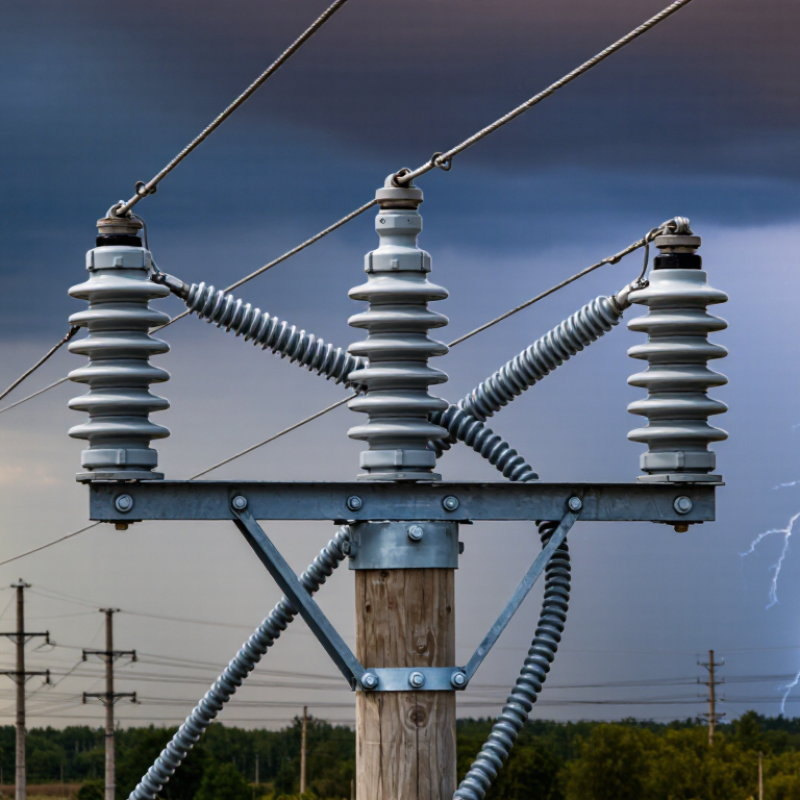
A Lightning Arrester is a quiet guardian installed between electrical conductors and the earth. When lightning or a switching surge raises voltage sharply, it provides a lower-resistance path to ground. The connected equipment then faces less stress. The arrester does not “stop” lightning. It limits dangerous overvoltage for a brief, critical moment.

The need is substantial. Vaisala’s Annual Lightning Report records billions of lightning events worldwide, confirming that electrical networks face frequent atmospheric stress. Industry standards, including IEC 60099-4 and IEEE C62.11, define important performance requirements for metal-oxide surge arresters. These include discharge behavior, energy handling, and temporary overvoltage capability. A rating alone does not tell the whole story.

Lightning researcher Dr. Vladimir A. Rakov describes lightning as “a complex physical phenomenon.” That observation matters in practical design. Cable length, grounding resistance, transformer location, pollution, and local lightning density can change the outcome. A small arrester beside a transformer may look adequate, yet poor grounding can leave dangerous residual voltage across insulation. The detail is easy to miss.

This guide explains how a Lightning Arrester works, where it belongs, and why coordination matters. It also examines voltage protection levels, surge current ratings, failure indicators, and maintenance practices. Some explanations simplify real behavior. That is intentional, but not perfect. Field conditions are rarely as tidy as a diagram. Reliable protection begins with standards, measured system data, and a willingness to question attractive specifications.
What Is a Lightning Arrester and How Does It Work?

Lightning Arrester Definition: IEC 60099-4 Metal-Oxide Surge Protection

What Is a Lightning Arrester and How Does It Work?

Lightning Arrester Definition: IEC 60099-4 Metal-Oxide Surge Protection

A lightning arrester limits dangerous overvoltage caused by lightning or switching events. It connects between a power conductor and ground. Under normal voltage, its leakage current remains very low. During a surge, metal-oxide varistors conduct heavily and divert energy away from protected equipment.

IEC 60099-4 specifies requirements for metal-oxide surge arresters without gaps. The standard addresses electrical performance, insulation coordination, energy capability, thermal stability, and verification tests. Engineers use these requirements when assessing residual voltage, temporary overvoltage, and long-term operating reliability. The arrester must withstand system conditions, not only a single lightning impulse.

Selection requires more than choosing a high voltage rating. Check the continuous operating voltage, system grounding, fault current, pollution level, altitude, and expected surge energy. Field technicians also inspect housing condition, connection torque, grounding paths, and signs of moisture or overheating. A loose earth connection can weaken protection significantly.

Small details matter. Very much.

A common mistake is treating every surge as identical. Switching surges may differ greatly from direct lightning currents. Installation geometry also affects protective performance, especially when connecting leads are long. IEC testing provides dependable evidence, but site conditions still require careful engineering judgment. No specification replaces inspection, coordination, and honest review of actual operating risks.

Lightning Overvoltage Sources: 1.2/50 μs Impulses and 30 kA Currents

A lightning arrester protects electrical equipment from short, dangerous overvoltage surges. It connects between a conductor and ground, remaining almost nonconductive during normal operation. When surge voltage rises sharply, its internal nonlinear element conducts excess current away from sensitive equipment. The voltage is then limited to a safer residual level. The path matters.

Lightning overvoltage is often represented by a 1.2/50 μs impulse. The first number describes the approximate voltage rise time. The second indicates the time until the voltage falls to half its peak value. This waveform helps engineers test insulation and protective devices under repeatable conditions. However, a natural lightning event rarely follows a perfect laboratory curve. Cable length, grounding, nearby structures, and multiple reflections can distort the surge.

A 30 kA lightning current represents a severe discharge, not a universal worst-case value. The arrester must conduct this current without rupturing, overheating, or losing its protective characteristics. Its energy rating, clamping voltage, and temporary overvoltage capability all matter. So does the installation. A long grounding lead can add inductive voltage during the surge. Poor bonding may leave equipment exposed, even when the arrester itself is correctly selected. In practical testing, engineers sometimes focus too heavily on peak current and overlook the complete current path. That assumption is convenient, but incomplete.

How the MOV Varistor Conducts: Nonlinear Resistance and Clamping Voltage

What Is a Lightning Arrester and How Does It Work?

A lightning arrester protects electrical equipment by diverting dangerous surge energy to ground. Its core component is often a metal-oxide varistor, or MOV. During normal operation, the MOV presents very high resistance. Only a tiny leakage current passes through it.

When a lightning impulse or switching surge raises the voltage, the MOV changes behavior quickly. Its resistance falls sharply as voltage increases. This nonlinear response allows the device to conduct surge current instead of letting the full voltage reach sensitive insulation. The MOV does not remove the surge completely. It limits the remaining voltage to a level called the clamping voltage.

Clamping voltage is not one fixed number. It depends on surge current, pulse duration, temperature, and the MOV’s previous stress. A higher current usually produces a higher clamping voltage. The real waveform is messier. Laboratory tests may use a short impulse, while field surges can vary widely. Technicians should compare the arrester’s continuous operating voltage, maximum discharge current, and energy rating with the installation conditions.

After repeated surges, the MOV can age. Its leakage current may rise, creating heat inside the protective housing. In severe cases, thermal damage can follow. That is why practical designs include suitable disconnection and grounding arrangements. A simple explanation can mislead: the MOV reacts extremely fast, but it is not indestructible. Its protection depends on correct voltage selection, short wiring paths, and reliable earthing.

Arrester Ratings Explained: MCOV, 8/20 μs Current, and Energy Capability

A lightning arrester protects electrical equipment by diverting surge current to ground. Under normal voltage, its metal-oxide blocks behave almost like insulators. During a lightning surge, their resistance drops sharply. The arrester then creates a low-impedance path, limiting the voltage across transformers, cables, and switchgear.

MCOV means Maximum Continuous Operating Voltage. It is the highest RMS voltage an arrester can withstand continuously without excessive leakage or thermal stress. MCOV is not simply the system’s nominal voltage. Engineers must check grounding, temporary overvoltage, and the actual voltage from line to earth. A small mistake here can shorten service life. I still recheck these values after reviewing a single-line diagram.

The 8/20 μs current rating describes a standard impulse waveform: the current rises near its peak in eight microseconds and falls to half that value in twenty. It helps compare discharge performance, but it is not the largest possible lightning current. Energy capability is equally important. It shows how much surge energy the arrester can absorb without thermal failure, often expressed in kilojoules per kilovolt. Longer surges and repeated events may create more heat than one sharp impulse. Installation details matter too. Short, straight leads reduce inductive voltage. A poor ground connection can undermine a correctly selected arrester. Real systems are less tidy than test laboratories.

What Is a Lightning Arrester and How Does It Work? - Arrester Ratings Explained: MCOV, 8/20 μs Current, and Energy Capability

A metal-oxide lightning arrester uses nonlinear zinc-oxide varistor blocks to remain highly resistive at normal system voltage and conduct surge current when an overvoltage occurs. The table below summarizes key rating dimensions and representative values used for engineering comparison.

Rating Dimension Meaning Representative Data or Range How It Affects Protection Important Selection Consideration
Maximum Continuous Operating Voltage (MCOV), Uc The highest specified continuous RMS voltage that may be applied across the arrester under normal operating conditions. 2.55–29.0 kV in common medium-voltage rating points. A higher MCOV improves temporary-overvoltage withstand but generally produces a higher protective voltage. MCOV must be equal to or greater than the actual continuous phase-to-ground voltage, including system voltage tolerance and grounding conditions.
Arrester Rated Voltage, Ur The manufacturer-declared voltage reference associated with the arrester’s temporary-overvoltage and operating-duty characteristics. 3–36 kV representative medium-voltage rating points. Provides a standardized reference for comparing arrester duty and temporary-overvoltage capability. Rated voltage is not the same as MCOV. The two values must be checked separately.
Nominal Discharge Current The crest value of the standard 8/20 μs current impulse used to classify and compare arrester discharge performance. 5 kA, 10 kA, or 20 kA are commonly encountered values. Higher nominal discharge current ratings generally indicate greater surge-current test capability, but they do not alone define the complete energy capability. Choose the value according to the installation’s lightning exposure, fault environment, coordination study, and applicable standard.
8/20 μs Current Waveform A standardized impulse current that reaches its peak in approximately 8 μs and decreases to half its peak value in approximately 20 μs. 8 μs virtual front time / 20 μs time to half-value Allows repeatable comparison of discharge voltage, current withstand, and protective behavior. The 8/20 μs waveform is not a complete model of every lightning event or switching surge.
Residual Voltage, Ures The voltage measured across the arrester while it conducts a specified impulse current. Must be specified at a stated current, such as 5 kA, 10 kA, or 20 kA. Lower residual voltage generally provides better insulation protection. Residual voltage should be coordinated with the equipment insulation withstand level and installation lead length.
Energy Capability The arrester’s ability to absorb and dissipate surge energy without thermal failure or loss of protective characteristics. Not represented by one universal kJ value; it depends on arrester design, voltage, current, duration, repetition, and applicable test class. Determines how well the arrester withstands repeated or high-energy surges and temporary overvoltages. Review the specified energy, charge, line-discharge class, switching-surge duty, and thermal-stability test information rather than relying only on kA.
Temporary Overvoltage (TOV) Capability The voltage-versus-time withstand capability during abnormal but temporary power-frequency overvoltage conditions. Must be evaluated as a voltage-time curve; it is not a single fixed voltage. Helps prevent arrester thermal runaway during ground faults, load rejection, resonance, or other system events. System grounding method and fault-clearing time are essential inputs for TOV coordination.
Response Behavior The arrester’s nonlinear change in resistance as voltage rises above its normal operating region. High resistance at normal voltage; low resistance during a surge Diverts surge current to ground and limits the voltage applied to protected equipment. Short, straight, low-inductance connections improve the practical protection level.

Representative MCOV and Rated-Voltage Pairs

Representative Rated Voltage, Ur Representative MCOV, Uc Approximate Uc / Ur Relationship Typical Engineering Use
3 kV 2.55 kV 0.85 Low-voltage or specialized medium-voltage protection systems
6 kV 5.10 kV 0.85 Systems with approximately 3.5 kV phase-to-ground operating voltage
10 kV 8.40 kV 0.84 Common medium-voltage distribution applications
12 kV 10.20 kV 0.85 Medium-voltage distribution and feeder protection
15 kV 12.70 kV 0.85 Medium-voltage distribution systems with higher line-to-ground voltage
18 kV 15.30 kV 0.85 Medium-voltage feeder, transformer, and cable protection
21 kV 17.00 kV 0.81 Higher-voltage distribution and substation applications
24 kV 19.50 kV 0.81 Medium-voltage substation and feeder protection
27 kV 22.00 kV 0.81 Higher-voltage distribution installations
30 kV 24.40 kV 0.81 Higher-voltage distribution and substation protection
36 kV 29.00 kV 0.81 Upper medium-voltage and substation applications
Engineering note: The MCOV pairs shown are representative rating points for comparison, not a substitute for a product datasheet or system coordination study. Actual available values, tolerances, discharge classes, protective levels, TOV curves, and energy ratings vary by design and applicable standard.
Unit guide: kV = kilovolt; kA = kiloampere; μs = microsecond; RMS = root mean square; TOV = temporary overvoltage.

Installation and Testing: IEEE Coordination, Grounding, and Leakage-Current Checks

A lightning arrester limits transient overvoltage by diverting surge current to ground. Correct installation starts with IEEE coordination, not simply choosing the highest discharge rating. IEEE C62.22 recommends comparing the arrester’s maximum continuous operating voltage, temporary overvoltage capability, and protective level with the equipment insulation level. Keep the margin practical. A large margin may reduce protection quality.

Lead length matters greatly. Use short, straight phase and ground conductors. Avoid sharp bends and coiled grounding wires. IEEE Std 80 uses a 50-kilogram body model when evaluating touch-voltage safety. The grounding grid must control both earth potential rise and accessible touch voltage. Bond metal enclosures, cable screens, and structural steel where the design requires it. Ground resistance alone is not enough.

Testing should begin with a visual inspection. Check cracked housings, loose terminals, moisture marks, and overheated connectors. Measure leakage current with a suitable instrument, preferably separating total and resistive components. There is no universal alarm value; temperature, voltage, arrester type, and aging affect readings. Record a baseline during commissioning, then compare identical conditions during maintenance. CIGRE Technical Brochure 549 emphasizes condition assessment through trend analysis rather than one isolated measurement. That is easy to overlook. A single normal reading can still hide gradual deterioration. Recheck after major storms, switching events, or grounding modifications.

What Is a Lightning Arrester and How Does It Work?

This representative 10 kA, 8/20 μs impulse-current waveform illustrates the surge diverted by a lightning arrester. Installation requires coordination between the arrester’s maximum continuous operating voltage, protective level, and the insulation withstand level of the protected equipment. A short, low-impedance grounding path is essential. Commissioning checks commonly include grounding continuity, connection tightness, physical condition, and leakage-current measurements compared with the arrester manufacturer’s limits and previous test records.